Tags: Directivity / Airy Disk / Dipole
![]() Why are parabolic reflectors as part of antenna systems so common? The reason is that they provide a very high directivity. In this problem you will learn about this very basic concept of antenna theory to quantify emitters and receivers at the examples of a dipole, a "half-dipole" and a parabolic reflector.
Why are parabolic reflectors as part of antenna systems so common? The reason is that they provide a very high directivity. In this problem you will learn about this very basic concept of antenna theory to quantify emitters and receivers at the examples of a dipole, a "half-dipole" and a parabolic reflector.
Problem Statement
 Calculate the directivity of a dipole oscillating in z direction. Then, assume the radiation propagating in negative x-direction gets absorbed in the farfield of the dipole. How does the directivity change?
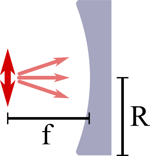
Now we want to put this “half-dipole” in the focal point of a parabolic reflector with opening radius R and focal distance f, see figure on the right.
How can we calculate the directivity of this device approximately for a small opening angle δθ = R/f.
Assume that the backreflected light is not influenced by the “half-dipole” itself. Calculate the directivity D for a wavelength λ = 500nm and an opening radius R = 20cm.
Hints
A plane wave with wavelength λ = 2π/k incident on a hole with radius a will cause an intensity profile
\[\begin{eqnarray*} I\left(\theta^{\prime}\right)&\propto&\left(\frac{2J_{1}\left(kR\sin\theta^{\prime}\right)}{kR\sin\theta^{\prime}}\right)^{2} \end{eqnarray*}\]
far away from the aperture (i.e. in the Fraunhofer approximation).
Here, θ' is the angle with respect to the direction of propagation and J1 is a cylindrical Bessel function. The first zero of this intensity is at the second one of this Bessel function, at kR·sin(θ') ≈3.83.
If an emitter has a single main lobe with an elliptical form, \(\Omega_{p}\) is approximately given by the product of the angles where the intensities in the main axis system are half of the maximum,
\[\begin{eqnarray*} \Omega_{p}&\approx&\alpha_{1}\alpha_{2}\ . \end{eqnarray*}\]
I hope everything is somewhat clear after the hints! Let us find the directivity of a parabolic reflector!
Let's first consider the calculation of directivity for the dipole and "half-dipole" to familiarize with the concept. Then we will come to the parabolic reflector where we will have to work a little more to find a meaningful expression for the directivity.
Dipole and “Half-Dipole”
For a dipole oscillating along the \(z\)-axis we have \(F_{d}\left(\theta,\varphi\right)=\sin^{2}\theta\), so
\[\begin{eqnarray*} D_{d}&=&\frac{4\pi}{\int_{0}^{2\pi}\int_{0}^{\pi}\sin^{3}\theta d\theta d\varphi}\\&=&\frac{4\pi}{2\pi\int_{0}^{\pi}\sin^{3}\theta d\theta d\varphi}\\&=&2/\left[-\frac{3}{4}\cos\theta+\frac{1}{12}\cos3\theta\right]_{0}^{\pi}\\&=&3/2\ . \end{eqnarray*}\]
For the given assumptions, the “half-dipole” is given by
\[\begin{eqnarray*} F_{hd}\left(\theta,\varphi\right)&=&\begin{cases}\sin^{2}\theta & \varphi\in\left[-\frac{\pi}{2},\frac{\pi}{2}\right]\\0 & \mathrm{else}\end{cases} \end{eqnarray*}\]if we accept negative \(\varphi\). Then, since the calculation is exactly the same as for the dipole except that the \(\varphi\) integration results in \(\pi\) rather than \(2\pi\), we find\[\begin{eqnarray*} D_{hd} = 2D_{d}=3\ . \end{eqnarray*}\]
The Parabolic Reflector
Now to the half-dipole in the focus of a prabolic reflector. If we consider this problem in the ray optics picture, we find for the radial part of the Poynting vector
\[\begin{eqnarray*} S_{r,\mathrm{refl}}\left(\theta,\varphi\right)&\propto&\delta\left(\theta-\pi/2\right)\delta\left(\varphi+\pi\right)\ . \end{eqnarray*}\]
This formula basically means that all of the energy is focussed in one point, represented by the delta-distributions which also implies \(D\rightarrow\infty\).
This is very bad from two perspectives. From a mathematical viewpoint, this energy density only makes sense inside an integral, i.e. for \(P_{\mathrm{rad}}\). But how to normalize the Poynting vector to obtain \(F\)?
Also from a physical point of view it is not really convincing since diffraction will cause the energy density to be distributed.
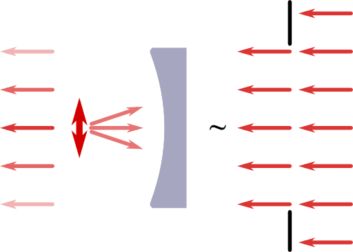 We may include this effect to find a somehow more meaningful directivity than just infinity: we may simply introduce the radius of the reflector as an effective circular aperture. We may further assume a plane wave illumination with constant amplitude, see figure on the left.
This additional approximation is very good if the opening angle \(\delta\theta \approx R/f \ll 1\) since the amplitude of the dipole \(\propto \sin \theta ^2\) is approximately constant. Otherwise, the intensity in the Fraunhofer diffraction would be more complicated to calculate. Then, the intensity around the axis of propagation and angle \(\theta^{\prime}\in\left[0,\pi\right]\) with respect to this axis is given by
\[\begin{eqnarray*} I\left(\theta^{\prime}\right)&\propto&\left(\frac{2J_{1}\left(kR\sin\theta^{\prime}\right)}{kR\sin\theta^{\prime}}\right)^{2}\ . \end{eqnarray*}\]
In our case, the propagation is along the negative x-axis. Now we may use that \(\Omega_{p}\) is approximately given by the product of the angles where the intensities in the main axis system are half of the maximum,
\[\begin{eqnarray*} \Omega_{p}&\approx&\alpha_{1}\alpha_{2}=\alpha^{2} \end{eqnarray*}\]
since \(\alpha_{1}=\alpha_{2}=\alpha\) in our axisymmetric intensity.
Then, \(\alpha\) is approximately given by the first root of the Bessel function,
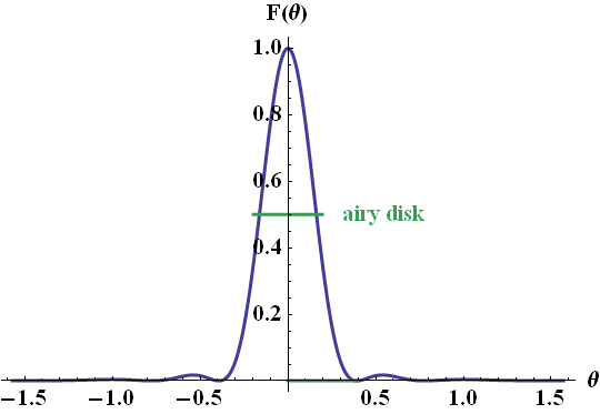
\[\begin{eqnarray*} kR\sin\alpha&\approx&3.83\ ,\ \mathrm{so}\\D_{hp}&\approx&\frac{4\pi}{\arcsin\left[3.83/kR\right]} \end{eqnarray*}\]
with \(k=2\pi/\lambda\). The diffraction pattern of a circular aperture is one of the basic concepts in diffraction theory - the angle \(\alpha\) even has a name and is called airy disk, see figure below:
Coming back to the small opening angle approximation, we can see now, that for higher \(\delta\theta\), the fall-off of the intensity of the dipole on the reflector would act as a "smooth aperture" itself and we would find an even stronger decay in the farfield intensity. In turn, the directivity would be higher and our result is hence a lower limit for the directivity.
If we take now for example \(R=20\,\)cm and \(\lambda=500\,\)nm, we find \(kR=2.5\cdot10^{6}\) and \(\alpha\approx1.5\cdot10^{-6}\). Then, the directivity of the parabolic reflector is given by\[\begin{eqnarray*} D_{hp}&\approx&5.4\cdot10^{12}\ . \end{eqnarray*}\]Well, this is still pretty much infinity. Nevertheless, this kind of result can be expected for such a small wavelength and this extremely big aperture since the intensity is basically a delta-peak.
In reality, an antenna will always have a lower directivity since it may be impossible to produce an ideal parabolic reflector. Surface roughness, position of the dipole, absorption by the source as geometrical obstacle will be the main fabrication limitations. There are also a few other things one has to bare in mind like the angular dependence of the reflection of the dipole's radiation, the losses in the reflector etc.
In the end, the directivity may be lowered by several orders of magnitude - but it will still be an absolutely impressive number. This lets us understand why parabolic antennas are indeed used in a lot of applications where directivity is extremely important like telescopes in astrophysics or as receiver for broadcast signals from satelites.
Background: Directivity in Antenna Theory
The radiated power \(dP_{\mathrm{rad}}\) into a certain angle \(d\Omega=\sin\theta d\theta d\varphi\) is related to the radial component of the time-averaged Poynting vector \(S_{r}\left(r,\theta,\varphi\right)\),
\[\begin{eqnarray*} dP_{\mathrm{rad}}&=&r^{2}S_{r}\left(r,\theta,\varphi\right)d\Omega\equiv r^{2}S_{r,\mathrm{max}}\left(r\right)F\left(\theta,\varphi\right)d\Omega\ . \end{eqnarray*}\]
As defined above, one may also normalize \(S_{r}\) und use the normalized radiation intensity \(F\) instead. This quantity is used to define the directivity \(D\) of a certain antenna or source,
\[\begin{eqnarray*} D&=&\frac{4\pi}{\Omega_{p}\equiv\int_{0}^{2\pi}\int_{0}^{\pi}F\left(\theta,\varphi\right)\sin\theta d\theta d\varphi}\ . \end{eqnarray*}\]
As you can see: what we have just discussed for a simple geometric form - the parabula - is a very important concept!